Creating a Bare Bones Bootloader
Upon hearing the word 'bootloader', many people cower in fear. It seems like a scary low-level thing that's very easy to mess up. To dispel some of this fear, I'm going to walk through making a super simple bootloader/OS, assuming only a basic level of familiarity with assembly language and how computers work.
The Plan
The first thing to understand or research if we're looking to write something to run when the computer starts up, is exactly what the boot process is. Typically computers will first boot into the BIOS (Basic Input/Output System) firmware, which performs some tests (often while showing a logo of sorts onscreen) and then boots into an operating system. There's also a new standard, UEFI, coming into play as an alternative to BIOS, but we aren't going to talk about that here.

More precisely, the standard BIOS boot process is as follows:
- The computer boots into the BIOS.
- The BIOS performs a Power-on Self-test (POST).
- Using information from POST, and BIOS configuration details, possible boot devices are selected.
- For disk drives (or similar devices), the first 512 bytes of the disk — termed the 'boot sector' — is considered for booting. If the sector can be read and the standard boot signature is present in the last two bytes (0x55 0xAA), the device is considered bootable. Otherwise, the next device in the list of candidates is checked.
- Assuming the disk drive is bootable, the 512 byte boot sector is copied to address 0x007C00 at which point the BIOS transfers control to the loaded sector through a jump instruction to 0x007C00.
When booting from partitioned devices, the boot sector of the drive will commonly be a Master Boot Record (MBR), in which case the boot sector generally consists of a bootstrap which identifies a certain partition on the drive — usually via a partition table (which may also reside in the first sector of the drive) — and proceeds to load the boot sector of that particular partition, sometimes called a Volume Boot Record (VBR). The structure of a number of modern MBR boot sectors is as follows:
0x7C00: Bootstrap
0x????: Disk Information
0x????: Partition Table
0x7DFE: Boot Signature (0x55 0xAA)
0x7E00:
In our case, however, dealing with disk partitions is a bit fancy and overcomplicated. Since complete control is handed to us when the BIOS jumps to our boot sector in RAM, we can just work with an unpartitioned disk and go straight into our Volume Boot Record in the first 512 bytes (the boot sector) of our disk image. Technically that means we're not really creating a bootloader, more of a really really really small operating system. Realistically though, what we're creating is exactly like a bootloader — just without the loading of and jumping into into some other portion of code on the disk, and so I'll continue referring to our bootloader as such. Thus the structure of our boot sector will be the code we want to execute, followed by the standard boot signature.
So the plan is that the BIOS will copy our boot sector to 0x007C00 and transfer control to this point, and then we... do something. Since we're just creating a bare bones bootloader, let's make our goal to output some text. Note that in the x86 BIOS process, the BIOS will transfer control while the processor is still operating in real-mode. This has its advantages and disadvantages, but to keep things simple here we'll just keep things in real-mode (keeping it real, bro) for the entirety of our bootloader.
With all this research and theory out of the way, let's actually write some code!
The Code
We're going to be using NASM here, because it happens to be the x86 assembler I'm most familiar with. Since x86 real-mode defaults to using 16-bit instructions, we want the assembler to output instructions as such. We can still use 32-bit registers if we so wish, but as we're operating in 16-bit mode we need to prefix any instructions that do this with the "Operand Size Override Prefix" (0x66). All of this is accomplished by using the 'BITS' NASM directive — in this case: BITS 16.
Addresses in x86 assembly are determined from the segment address plus an offset. As both real and protected mode of the x86 processor use 16-bit segment registers, we should ensure that our segments — in particular the stack segment (ss) and data segment (ds) — refer to sensible 64K regions. Since real-mode limits absolute addresses/offsets to 16-bits in length, segments can help us access more than one 64K portion of memory.
Regardless of whether we'll make explicit use of the stack segment in this example, it seems good practise to set up a stack — especially given that some instructions make implicit use of segments (e.g. push, which uses the Stack Segment with a Stack Pointer offset), and it would be irresponsible not to define a stack if the bootloader were to be expanded beyond our basis of outputting some text.
In this case, I'm going to structure our bootloader such that it has a 4K stack just after the location of the boot sector in memory. Remember that the boot sector is loaded into 0x7C00 and is 0x200 (512) bytes long, and so we want our stack to reside just after this. Due to the way that segments work in x86 assembly (they refer to 64K chunks of memory, not specific locations, as noted previously), we actually want to divide both of those values by 16 before assigning the final location to the stack segment — Effective Address = Segment*16 + Offset. So the code to set up our stack segment is as follows:
mov ax, 07C0h   ; Set 'ax' equal to the location of this bootloader divided by 16
add ax, 20h     ; Skip over the size of the bootloader divided by 16
mov ss, ax      ; Set 'ss' to this location (the beginning of our stack region)
Since space is often precious in a mere 512 bytes, assuming we don't get the assembler to optimise this code it might be more appropriate to save a few bytes by doing the add instruction manually, and simply changing the mov to mov ax, 07E0h. I'll keep things as they are for now though since keeping the add separate offers more clarity to what we're actually doing.
As noted previously, operations involving the stack involve the stack pointer offset from the stack segment: SS:SP. As the stack pointer grows downwards in memory address (i.e. towards 0x00) by default, we want to define the stack pointer to point to the bottom of the stack which is 4K away from our stack segment: mov sp, 4096. At this point our bootloader memory footprint should look like the following:
        |ˆˆˆˆˆˆˆˆˆˆˆˆˆˆˆˆˆ|
0x7C00: |-----------------|
        |   Boot Sector   |
0x7E00: |-----------------| <-SS
        |                 |
        |                 |
        |   Stack Space   |
        |                 |
        |                 |
0x8E00: |-----------------| <-SS:SP (grows upwards)
        |                 |
         ˇˇˇˇˇˇˇˇˇˇˇˇˇˇˇˇˇ
With regards to the data segment, we can just set the segment to the start of our bootloader code. Remember that the real purpose of segments in real-mode is to allow us to access more than a single 64K of data (in real-mode, there is a little over 1MB of addressable memory — 0xFFFF0 + 0xFFFF bytes to be exact), and any static or global data in our little bootloader will most definitely live within our little 512 codebase. So with the ds pointed towards the start of our bootloader code, we can definitely access all of the data we might need to in Segment:Offset form. Thus the code to initialise our data segment:
mov ax, 07C0h   ; Set 'ax' equal to the location of this bootloader divided by 16
mov ds, ax      ; Set 'ds' to the this location
From here, we can actually go ahead and do something interesting before we tie up. As we're in real-mode and haven't specified any custom interrupt handling, we can make use of some standard BIOS interrupts to accomplish tasks. Looking at the list on Wikipedia, the 'Video Services' interrupt 10h seems interesting. Upon closer inspection, the interrupt when AH is 0Eh seems particularly interesting as it provides teletype output. Looking at the particular parameters for this interrupt it seems that AL should contain the character to be printed to the screen, BH should contain the page number, and BL should contain the colour (only in graphic mode). Thus writing assembly to print a string using int 10h from here is trivial.
Perhaps in the context of our bootloader it makes sense to write a proper routine for writing strings which expects a single parameter — the address of a null-terminated string — through the si (Source Index) register. The next portion in our bootloader code will hence be to call this routine (which we'll name 'print'), and stop execution such that our string remains on the screen and nothing else happens:
mov si, message	; Put address of the null-terminated string to output into 'si'
call print      ; Call our string-printing routine
cli             ; Clear the Interrupt Flag (disable external interrupts)
hlt             ; Halt the CPU (until the next external interrupt)

message db 'This was outputted by a basic bootloader!', 0
Now we just need to define our print function to make use of the standard BIOS interrupt 10h previously described:
; Routine for outputting string in 'si' register to screen
print:
	mov ah, 0Eh     ; Specify 'int 10h' 'teletype output' function
	                ; [AL = Character, BH = Page Number, BL = Colour (in graphics mode)]
.printchar:
	lodsb           ; Load byte at address SI into AL, and increment SI
	cmp al, 0
	je .done        ; If the character is zero (NUL), stop writing the string
	int 10h         ; Otherwise, print the character via 'int 10h'
	jmp .printchar  ; Repeat for the next character
.done:
	ret
Now we've finished writing the main bulk of the code, we just need to pad the code out with 0s to byte 510, and then use bytes 511 and 512 for the standard byte signature (as previously mentioned, 0x55 and 0xAA — which we'll specify backwards in our code due to little endian byte order). Using the NASM times directive for the padding, we can do all of this with the following:
; Pad to 510 bytes (boot sector size minus 2) with 0s, and finish with the two-byte standard boot signature
times 510-($-$$) db 0
dw 0xAA55           ; => 0x55 0xAA (little endian byte order)
And we're done! We finished writing our little bootloader — the final product of which, 'bootloader.asm', is broadly as follows:
BITS 16

start:
	; Set up 4K stack after this bootloader
	; [Remember: Effective Address = Segment*16 + Offset]
	mov ax, 07C0h   ; Set 'ax' equal to the location of this bootloader divided by 16
	add ax, 20h     ; Skip over the size of the bootloader divided by 16
	mov ss, ax      ; Set 'ss' to this location (the beginning of our stack region)
	mov sp, 4096    ; Set 'ss:sp' to the top of our 4K stack

	; Set data segment to where we're loaded so we can implicitly access all 64K from here
	mov ax, 07C0h   ; Set 'ax' equal to the location of this bootloader divided by 16
	mov ds, ax      ; Set 'ds' to the this location

	; Print our message and stop execution
	mov si, message ; Put address of the null-terminated string to output into 'si'
	call print      ; Call our string-printing routine
	cli             ; Clear the Interrupt Flag (disable external interrupts)
	hlt             ; Halt the CPU (until the next external interrupt)


data:
	message db 'This was outputted by a basic bootloader!', 0


; Routine for outputting string in 'si' register to screen
print:
	mov ah, 0Eh     ; Specify 'int 10h' 'teletype output' function
	                ; [AL = Character, BH = Page Number, BL = Colour (in graphics mode)]
.printchar:
	lodsb           ; Load byte at address SI into AL, and increment SI
	cmp al, 0
	je .done        ; If the character is zero (NUL), stop writing the string
	int 10h         ; Otherwise, print the character via 'int 10h'
	jmp .printchar  ; Repeat for the next character
.done:
	ret


; Pad to 510 bytes (boot sector size minus 2) with 0s, and finish with the two-byte standard boot signature
times 510-($-$$) db 0
dw 0xAA55	        ; => 0x55 0xAA (little endian byte order)
This code, along with the bits I use to compile and test the bootloader can be found at the associated GitHub repo, here.
Testing The Code
Now we've actually finished writing our bootloader, we need some way to test it. I use Vagrant with a 'lucid32' box for all my OS testing, but in this case you might be able to get by in your local environment. You can first compile the NASM via something along the lines of nasm -f bin -o bootloader.bin bootloader.asm, and you can then use a utility such as 'dd' to copy the data to a floppy disk image file (or to a real floppy disk!): dd conv=notrunc bs=512 count=1 if=bootloader.bin of=bootloader.flp. Using QEMU, you could then boot the floppy disk image in a virtual machine with something like qemu -fda bootloader.flp -curses. And voilà, it works.
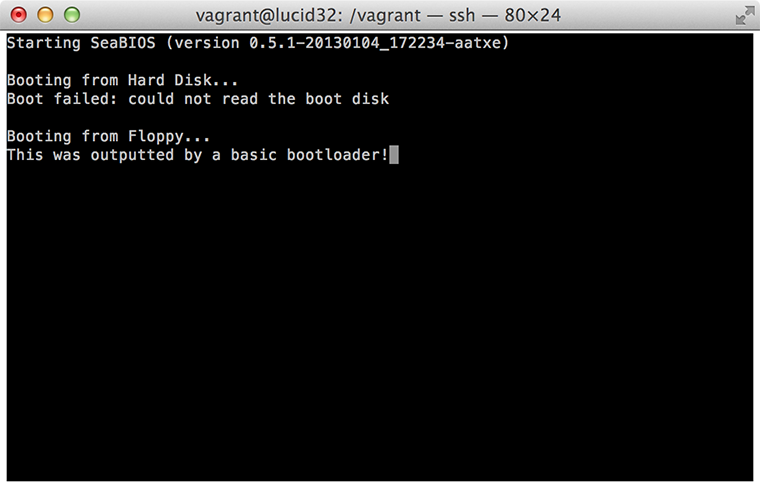
Now, I appreciate that this seems like an awful lot of work for a single line of text. There certainly is a fair bit of theory behind this, but at the end of the day the resulting assembly is actually relatively simple, and we've created a disk sector that a real x86 BIOS could boot into. If you wanted to actually test this 'properly', you could apply the disk image in the correct manner to a USB stick, floppy disk, or CD, and actually boot your computer into our little bootloader. Into our little world from which we have full CPU control and a number of powerful extensions could easily be added. If you're looking for some cool extensions you could add right now (still in real-mode), just take a look at some of the other standard BIOS interrupts, or alternatively you could start looking at other more complex bootloader goals.
Generally if you're interested in writing the core of an operating system, I'd actually suggest that you start out by using GRUB, which takes care of the process of taking control and switching into protected mode for you in a very standardised way (this is a pretty nice tutorial for getting started writing a very basic kernel which boots from GRUB). There's something interesting to me, however, about being able to write the code to actually take control — from the very first stage — all on our own, and that's exactly what we've achieved here.